
 English
 中文
中文 العربية
 español

Introduction
Why direct-to-chip liquid cooling is moving mainstream in 2026
The shift isn’t ideological—it’s arithmetic. AI/HPC clusters are pushing sustained rack power into ranges where air becomes the bottleneck: fan power rises, allowable ΔT narrows, and “hot aisle containment plus more airflow” stops scaling cleanly. Direct-to-chip liquid cooling (cold plates on CPUs/GPUs with a coolant loop back to a cooling distribution unit, or CDU) is moving from pilot-only territory to an operator default for dense pods because it turns a room-level airflow problem into a controllable fluid-distribution problem.
Decision lens: uptime, density, PUE/WUE, and TCO
Operators evaluating direct-to-chip should treat it as a facility + IT system change, not a component swap. The decisions that matter most in 2026 tend to fall into four buckets:
-
Uptime risk: leak prevention/detection, isolation strategy, commissioning discipline, redundancy.
-
Density headroom: how much heat the liquid loop actually captures vs what still spills into air.
-
Efficiency: PUE/WUE impacts from reduced fan energy, higher water temperatures, and chiller lift.
-
TCO: CapEx for CDUs/loops + integration vs avoided white space expansion, deferred electrical upgrades, and operational stability.
What this guide covers and how to use it
This guide walks through the 2026 state of direct-to-chip, compares architectures and CDU placements, then gets practical: facility integration, interoperability, reliability/maintenance, ROI and heat reuse, and a phased retrofit playbook for US sites.
The 2026 State of Direct-to-Chip
Adoption drivers and rack densities
The near-term driver is simple: higher sustained rack density. Multiple industry writeups in the last 24 months point to liquid cooling moving from “nice to have” to “necessary” as AI rack power climbs; for example, CyrusOne cites industry expectations of rapid adoption growth and frames liquid cooling as a response to rising density and efficiency pressure in hyperscale builds (CyrusOne, “in-rack and direct-to-chip cooling”).
A practical operator heuristic in 2026 is:
-
Below ~20–25 kW/rack: you may still win with advanced air/RDHx, depending on room constraints.
-
Around ~30–40 kW/rack and above: direct-to-chip becomes the cleanest way to scale without turning airflow into an operational tax.
-
Above ~80–100 kW/rack: expect liquid to carry the majority of heat, and plan the residual air path intentionally (you’re not “done with air,” you’re right-sizing it).
Heat removal fractions and airflow impact
Direct-to-chip rarely removes 100% of rack heat. Even in liquid-cooled deployments, there are non-chip components (memory, VRMs, NICs, drives) and structural losses that still need an air path. A peer-reviewed analysis in Energy Science & Engineering notes that “a fraction of liquid-cooled components between 0.6 and 0.9 is common” in direct liquid-cooled data centers (Wiley, 2025).
Operationally, that implies three design requirements operators often underestimate:
-
You still need an airflow model (and measurement) for the residual heat.
-
Room controls change: you’re managing both dew point and residual supply/exhaust paths.
-
The failure mode shifts: a pump degradation can turn “quietly reduced margin” into “rapid thermal runaway” faster than classic CRAC drift.
Supply/return temperatures and condensation control
In 2026, “warm-water” operation is no longer exotic; it’s increasingly a target because it improves economization options and makes heat reuse feasible. Many designs aim for supply temperatures that keep cold surfaces safely above dew point while still meeting cold-plate inlet requirements.
Condensation control is a controls problem first, and a hardware problem second:
-
Instrument dew point where it matters (near racks and in the return path), not only in a generic room sensor.
-
Interlock logic: enforce minimum coolant supply temperature as a function of measured dew point (with guard bands).
-
Commissioning baseline: document the exact dew point setpoints, alarm thresholds, and fail-safe behavior before you scale beyond a pilot.
Warning: If your design requires coolant below room dew point, you’ve committed to strict humidity control and fast interlocks. Treat that as a reliability dependency, not a comfort setting.
Architectures and CDUs for Direct-to-Chip Liquid Cooling
Single-phase cold plates and manifolds
Most operator deployments in 2026 favor single-phase cold plates because they’re predictable: the coolant stays liquid, heat transfer is stable, and maintenance/troubleshooting resembles industrial hydronics more than refrigeration.
Key practical considerations:
-
Manifold design and routing discipline matter as much as the cold plate itself. A great cold plate can be undermined by poor hose management, bad QD selection, or uneven flow balancing.
-
Pressure drop budgeting should be treated like an availability requirement. If you’re running too close to pump head limits, you’ll “pay” during filter loading, connector aging, or partial blockages.
Liquid-to-liquid vs liquid-to-air CDUs
A CDU isn’t just a heat exchanger—it’s a control boundary between IT coolant loops and the facility.
-
Liquid-to-liquid (L2L) CDU: rejects heat into a facility water loop. This is the most common pathway for high-density scaling because it decouples rack heat from room air constraints.
-
Liquid-to-air (L2A) CDU: rejects heat to air (often into the room or a dedicated airstream). This can be attractive for pilots or constrained brownfield sites where tying into facility water is difficult, but it tends to be less scalable for dense AI pods.
Decision framing operators actually use:
-
Choose L2L when you need repeatability, row/pod scaling, and future heat reuse.
-
Choose L2A when you need a contained pilot with minimal facility water rework (and you can tolerate the heat being dumped back into air).
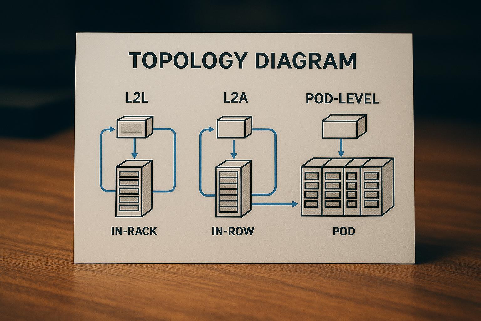
In-rack, in-row, and pod-level designs
Placement is an operational trade-off between distribution complexity and fault domain size:
-
In-rack: tight fault domain, short runs, but more distributed hardware to maintain.
-
In-row: balances serviceability and distribution; can align with row-level redundancy patterns.
-
Pod-level: simplifies standardization for AI pods, but a single CDU can become a larger shared dependency if not designed with redundancy and bypass.
Facility Integration and Interoperability
Facility water loop temperatures and flow ranges
Treat facility water integration as an envelope problem:
-
Temperature envelope: what supply temperatures can your facility loop reliably deliver year-round, and what does that do to economizer hours?
-
Flow envelope: what flow rates can you sustain per pod without creating pump instability, noise, or control hunting?
-
Approach temperature: your CDU heat exchanger approach is effectively “tax” on how warm your return can be and how viable heat reuse becomes.
The most important integration discipline is documenting the operating ranges as an interface spec: minimum/maximum facility supply temp, allowable ΔP across the CDU, acceptable water quality, and alarm/response behavior.
QDs, filtration, and sensor baselines (OCP-aligned)
Interoperability in direct-to-chip lives in the unglamorous details: connectors, cleanliness, and instrumentation.
-
Quick disconnects (QDs): Many operator discussions reference standardized concepts like Universal Quick Disconnect (UQD) and blind‑mate couplings for rack applications (for example, Danfoss’ overview of UQD couplings for rack applications). The practical point is standardization: if you can’t swap a server sled or manifold without a custom coupling story, your maintenance model won’t scale.
-
Filtration and cleanliness: Plan filtration as a lifecycle system, not commissioning theater. Filters load, pressure drop rises, and “normal” becomes uncertain unless you trend it.
-
Sensor baselines: Commissioning should establish baseline bands for supply/return temperature, per-branch flow (or at least per-manifold), and differential pressure across critical elements (filters, CDUs, manifolds). A baseline you don’t record is a baseline you don’t have.
DCIM/BMS integration and controls strategy
Your controls strategy should answer one operator question: What happens automatically at 2 a.m. when something drifts out of spec?
Minimum integration set:
-
DCIM/BMS visibility into: supply/return temps, flow, pressure, leak detection status, pump state, valve positions, and dew point.
-
Alarm taxonomy that separates “efficiency drift” from “availability risk.”
-
Control authority boundaries: decide whether the CDU is a local closed-loop controller with supervisory setpoints, or whether the BMS is commanding everything.
Coolnet integration note (interoperability for phased retrofits): For mixed estates, operators often benefit from modular, interoperable cooling + power + monitoring building blocks that can be introduced pod-by-pod without forcing a full-site rip-and-replace. Coolnet positions its integrated data center approach around deployable blocks that support staged upgrades—useful when you need phased retrofit execution while keeping a consistent monitoring and controls model across old and new infrastructure (Coolnet).
Reliability, Maintenance, and Risk
Fluid chemistry, corrosion, and cleanliness
Reliability starts with fluid discipline:
-
Compatibility matrix across metals, elastomers, and any additives; avoid “mystery mixes” across vendors.
-
Sampling and trending: define what you test (conductivity, inhibitors, particulates) and at what cadence.
-
Make-up fluid policy: who is allowed to top off, what’s the approval path, and how is it recorded?
Even a technically correct design degrades if cleanliness isn’t operationalized.
Leak prevention, detection, and isolation
Treat leak events as inevitable; design so they’re non-catastrophic:
-
Prevention: connector selection, torque procedures, hose routing that prevents abrasion and bend fatigue.
-
Detection: choose detection methods (point sensors, drip trays, conductivity tapes, dye-based inspection where appropriate) and integrate alarms into the same operator console that receives UPS and fire alerts.
-
Isolation: define the fault domain—can you isolate at the rack? the manifold? the pod? Practice the isolation procedure before you need it.
Hybrid sites and change management
Most operators in 2026 will run hybrid sites for years: some rooms stay air-first, some rows become liquid-ready, and AI pods sit next to conventional loads.
Change management that works in practice:
-
Train the cross-functional team (facilities + IT + vendors) on the “new normal” failure modes.
-
Update MOPs/SOPs to include coolant loop operations, baseline checks, and post-maintenance verification.
-
Treat inventory differently: QDs, hoses, seals, filters, and sensors become “availability spares,” not procurement afterthoughts.
ROI, KPIs, and Heat Reuse
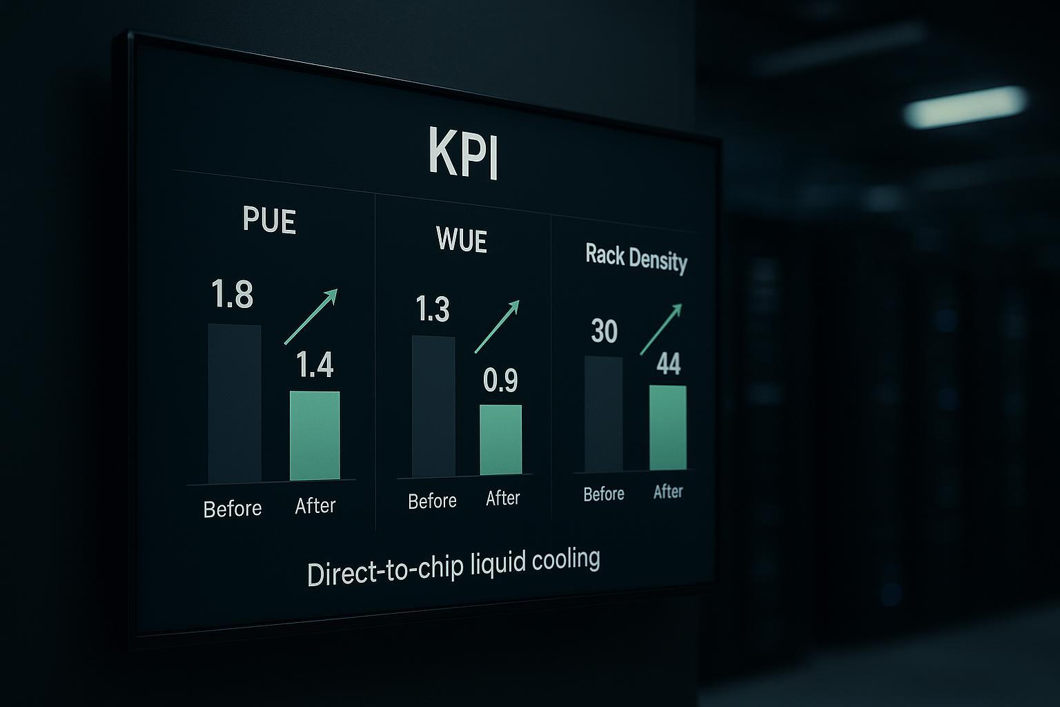
PUE/WUE shifts with direct-to-chip liquid cooling
The KPI shifts depend on your starting point, climate, and loop temperatures. But the mechanism is consistent:
-
Lower server fan power (and less room air movement) reduces energy overhead.
-
Higher coolant temperatures can reduce chiller lift and expand economizer hours.
-
The water story is nuanced: some designs shift water usage from humidification/evaporation patterns, while warm-water/dry cooler strategies can reduce WUE.
TCO and 2–4 year payback scenarios
Payback in the 2–4 year range is most plausible when at least one of these is true:
-
You avoid building new white space by densifying an existing footprint.
-
You can defer electrical upgrades by improving thermal efficiency and reducing fan power.
-
You reduce operational incidents caused by thermal stress (hard to model, but real in practice).
The caution: treat “payback” as a scenario analysis, not a promise. Use conservative assumptions and explicitly price in commissioning, spares, and staff training.
Warm-water loops and heat recovery opportunities
Heat reuse becomes realistic when your return temperatures are consistently warm enough to be useful. That’s where direct-to-chip can change the conversation: you can produce a more stable, higher-grade heat stream than typical air cooling.
Practical operator opportunities include:
-
Preheating for building systems (where permitted and economically rational)
-
District energy tie-ins (rare, but increasingly discussed)
-
Internal process heat for adjacent industrial loads
Phased Retrofit Playbook (US Context)
Phase 0 readiness and AHJ engagement
Before you buy hardware, align stakeholders and constraints:
-
Establish the interface spec between IT coolant loops and facility water.
-
Map code and safety implications (leak containment, egress, electrical separation, detection/alarming).
-
Engage the AHJ early with clear documentation: drawings, materials, and planned operational controls.
Pilot pod (L2A or isolated L2L) and validation KPIs
A pilot should answer specific questions with measurable outputs:
-
Thermal stability: can you hold chip inlet targets under sustained AI load?
-
Control stability: do pumps/valves hunt, and can you tune it out?
-
Reliability readiness: can the team detect, alarm, and isolate a simulated leak quickly?
-
Operational load: what’s the real maintenance and training burden?
Validation KPIs to record:
-
Supply/return temperatures and variability
-
Flow and differential pressure trends
-
Dew point excursions and interlock events
-
Unplanned interventions per week
-
Any impact on room airflow / hot spots
Scale-out, standardize, and optimize for heat reuse
Once the pilot is stable:
-
Standardize CDU placement patterns and connector choices.
-
Freeze a commissioning checklist and baseline template.
-
Expand to additional pods with the same control logic, alarm taxonomy, and spares model.
-
If heat reuse is in scope, add metering and a simple heat-balance model early so you can prove value.
Conclusion
Key takeaways and 2026 action priorities
Direct-to-chip is mainstream in 2026 because it lets operators scale density without turning airflow into an endlessly fragile constraint. The operators who win with it are the ones who treat it as an integration + controls + maintenance system—not just “new cooling hardware.”
RFP checklist pointers and interoperability must-haves
When you turn this into procurement language, push for clarity on:
-
Defined operating envelopes (temps/flows/ΔP) and commissioning baselines
-
Redundancy and isolation boundaries (rack/row/pod)
-
Interoperable connectors/QDs and documented maintenance procedures
-
DCIM/BMS integration points, alarm taxonomy, and fail-safe behavior
-
Fluid management plan (compatibility, sampling cadence, contamination controls)
Next steps to de-risk pilots and accelerate scaling
If you’re planning a pilot pod, start with an interface spec and a validation KPI sheet, then run a simulated fault drill (leak + pump degradation) before you scale.
If you want a reference architecture for interoperable cooling‑power‑monitoring blocks that support phased retrofits, explore how Coolnet approaches integrated data center building blocks and standardization across mixed estates.


 IPv6 network supported