
 English
 中文
中文 العربية
 español

Introduction
AI is rewriting the thermal math inside data halls. The shift isn’t just “hotter chips.” It’s sustained, rack-level heat loads that make airflow and fan power the limiting factors long before you run out of floor space.
In 2026, operators are moving from enhanced air (containment, higher ΔT, better airflow management) to liquid-assisted and liquid-first architectures because it’s the most practical way to hit three simultaneous objectives: density, efficiency, and predictable uptime.
This guide is for teams making real decisions: where AI data center liquid cooling fits compared with enhanced air approaches, which thresholds tend to trigger the move, and how to plan KPIs (PUE/WUE/ERF) and retrofit paths without betting the facility on a single cutover.
Density realities in 2025–2026
Rack power trends and thresholds
Operators aren’t dealing with a smooth curve. The change looks more like a step function: legacy estates built around “comfortable” air-cooled densities, plus new AI blocks that push well beyond what the room’s airflow architecture was designed to support.
A useful way to frame thresholds is by asking: what do you have to do to keep inlet temperatures stable as rack heat climbs? At higher densities, you’re not just adding cooling—you’re adding airflow. And that’s where air hits its wall.
According to Introl’s 2025 analysis of high-density GPU racks, airflow requirements scale aggressively at ~50 kW/rack, and fan power rises rapidly as airflow increases because it grows roughly with the cube of fan speed (“Liquid Cooling vs Air: The 50kW GPU Rack Guide” (2025)).
Practically, many teams treat these as decision bands:
-
≤15–20 kW/rack: enhanced air remains viable (containment, good cable discipline, tuned CRAH/CRAC, right-side economization).
-
~20–40 kW/rack: air becomes fragile—hot spots, recirculation sensitivity, and fan energy spikes make outcomes inconsistent across rows.
-
~30–50 kW/rack: “hybrid” territory becomes common (rack-level heat capture with liquid assist).
-
50 kW/rack and above: liquid-first approaches become increasingly hard to avoid if uptime and efficiency targets are non-negotiable.
When air hits limits and hybrids begin
Air doesn’t fail because operators forget containment. It fails because the work of moving heat via air becomes operationally expensive and physically messy:
-
High airflow increases acoustic, vibration, and maintenance burden.
-
Containment effectiveness becomes a system property—one compromised tile, blanking panel gap, or cable bundle can cascade into recirculation.
-
The facility ends up paying for cooling twice: once via room air systems, and again via server fan power.
That’s why hybrid approaches show up first in brownfield sites:
-
Capture the hottest fraction of the load with liquid (at the rack or chip).
-
Keep some air for the remaining components and for mixed-density rows.
As CoreSite notes in a 2025 operator-focused overview, hybrid air + liquid cooling is common during transition, with RDHx and DTC often deployed alongside existing air infrastructure (“Liquid Cooling steps up for high-density racks and AI workloads” (2025)).
Mapping densities to liquid choices
Think in terms of how much heat you must remove with liquid rather than just a rack kW number.
A practical mapping:
-
Bridge solution (moderate density, retrofit-friendly): rear-door heat exchangers (RDHx) to capture most exhaust heat without rebuilding the whole room.
-
Primary solution (high density, predictable scaling): direct-to-chip (DTC) cold plates that capture the majority of CPU/GPU heat at the source.
-
Ultra-dense / specialty deployments: single-phase immersion, where the hardware and operations model supports it.
Key Takeaway: Your first architecture decision is not “air vs liquid.” It’s “how much heat must be captured by liquid to make the room stable at your target density?”
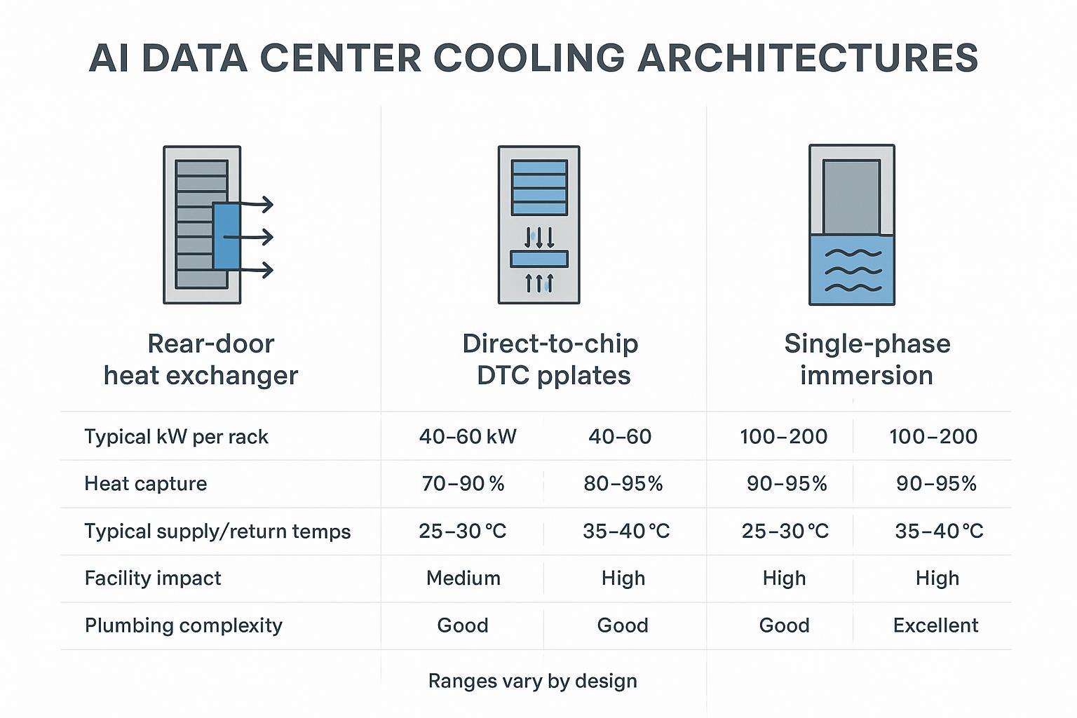
Cooling architectures compared
Rear-door heat exchanger (RDHx)
RDHx replaces (or adds) a heat exchanger at the rear of the rack, using facility water to absorb heat from the server exhaust stream before it re-enters the room.
Where RDHx tends to fit best:
-
Brownfield rows where you need incremental deployment.
-
Mixed-density rooms where you can’t standardize every rack overnight.
-
Bridge-to-DTC strategy: stabilize thermals now while you prepare for deeper liquid integration.
Typical operator considerations:
-
Facility impact: plumbing to the row/rack + flow control + leak detection.
-
Air remains part of the system: servers still push air through components; you’re just intercepting heat more effectively.
-
Control integration matters: maintaining stable return temps and alarm thresholds keeps RDHx from becoming a “mystery radiator.”
For a vendor-neutral overview of RDHx as an incremental option, see Coolnet’s Liquid cooling product overview, which includes “chilled water rear door heat exchanger” as a supported architecture.
Direct-to-chip (DTC) cold plates
DTC uses liquid-cooled cold plates mounted directly on high-heat components (typically CPUs/GPUs), moving most of the thermal load into a liquid loop.
Why DTC is the workhorse for AI in 2026:
-
It captures the majority of heat at the source, reducing room airflow requirements.
-
It’s compatible with many modern AI server designs that assume liquid at higher densities.
-
It creates a more measurable thermal system: supply/return temps, flow rate, approach temp, and heat rejection can all be monitored precisely.
Design cues that tend to separate “works in a lab” from “runs in production”:
-
Clear boundary between facility water and technology cooling system via a CDU heat exchanger.
-
Redundancy strategy (pumps, sensors, controls) aligned to your SLA.
-
Serviceability (filters, isolation valves, drain/fill strategy, hose routing, quick connects).
For a reference point on a cold-plate approach, Coolnet’s Cold Plate Liquid Cooling Solution page outlines the architecture at a high level.
Single-phase immersion systems
Single-phase immersion submerges IT hardware in a dielectric liquid that absorbs heat directly. The warmed fluid is circulated through a heat exchanger to reject heat to facility water.
Immersion can be compelling when:
-
You need very high density and can standardize hardware models.
-
Your operations team is prepared for a different maintenance workflow.
-
You’re optimizing for reduced server fan power and potentially simpler room airflow.
Immersion can be challenging when:
-
Hardware compatibility is uneven (OEM acceptance, warranties, board coatings, connectors).
-
Maintenance practices aren’t ready (lifting/handling, drip management, fluid QA).
-
Supply chain and fluid handling plans aren’t mature.
For an example architecture description, see Coolnet’s Immersion Liquid Cooling Solution.
Efficiency and heat reuse outcomes
Site PUE impact and fan/pump trade-offs
At higher rack densities, efficiency isn’t only about the chiller. It’s also about where the work happens:
-
Air systems pay an ongoing tax in server fan power and in moving large volumes of air.
-
Liquid systems shift some work to pumps, but they can reduce fan power and stabilize inlet conditions.
The critical trade-off to model is not “fans vs pumps” in isolation—it’s total facility + IT power under real load profiles.
For broader context on efficiency principles and measurement, the U.S. Department of Energy’s Best Practices Guide for Energy-Efficient Data Center Design (2024) is a helpful baseline reference.
WUE strategies and dry-cooler options
In 2026, water is an operational constraint in many regions, not just a sustainability talking point. Liquid cooling does not automatically increase water use—the heat rejection method does.
Practical WUE strategies operators are using:
-
Prefer closed-loop, dry cooler designs where climate and supply temperatures allow.
-
Run warmer supply water when the IT stack supports it (increasing economization hours).
-
Use cooling towers selectively and with clear make-up water accounting, especially in water-stressed markets.
The operational takeaway is simple: design WUE like you design redundancy—explicitly, with measurement and alarms.
Enabling heat reuse and ERF gains
Liquid makes heat reuse less theoretical because it can deliver higher-grade heat at useful temperatures—especially in warm-water configurations.
ERF (Energy Reuse Factor) becomes realistic when:
-
There is a nearby sink (district heating, industrial process, building heating).
-
Supply/return temperatures are high enough to avoid excessive lift.
-
Controls can maintain stability during load swings.
If you’re considering reuse, treat it as a separate workstream: metering, contracts, and operations ownership matter as much as the heat exchanger.
Implementation and reliability essentials
CDUs, secondary loops, and controls integration
In most production deployments, the CDU is the boundary device that makes liquid cooling manageable:
-
It separates facility water from the technology loop via a heat exchanger.
-
It provides pumping, filtration, expansion management, sensor instrumentation, and control logic.
-
It becomes the control point for maintaining supply temperature, flow rate, and alarm limits.
A common reliability-first pattern is:
-
Primary loop: facility water (or condenser water) feeding the CDU.
-
Secondary loop: technology coolant loop feeding manifolds, RDHx, cold plates, or immersion tanks.
This is also where integration discipline pays off:
-
Tie CDU telemetry into BMS/DCIM so alarms aren’t trapped in a local HMI.
-
Standardize tags and thresholds across pods/rows so your NOC sees one consistent picture.
-
Define “done” commissioning checks: stable ΔT under load, leak detection verification, redundancy switchover tests, and sensor calibration.
Coolnet example (neutral): Coolnet positions its liquid cooling building blocks around CDUs and modular, repeatable deployment packaging. Its product documentation describes CDUs spanning 40 kW to 2000 kW, redundancy concepts (such as dual-pump configurations), and controls/telemetry options including Modbus integration. For a practical starting point, see Coolnet’s overview of what a coolant distribution unit (CDU) does (linked once here) and its broader integrated deployment framing in the integrated data center solutions overview for multi-site rollouts.
Redundancy, leak detection, and serviceability
Liquid reliability is built from boring, repeatable controls:
-
Redundancy: define what is N+1 (pumps, power feeds, controls) and what is not.
-
Leak detection: deploy at the right granularity (rack/row), and test the end-to-end alarm path.
-
Isolation and serviceability: valves, dripless quick connects, drain/fill procedures, accessible filters.
-
Spare parts and training: leaks and sensor failures aren’t “rare events” at scale—they’re operations.
Warning: Avoid “pilot-only” engineering. If the pilot’s fittings, hose routing, labeling, and alarm paths aren’t production-grade, scale-out will multiply friction and risk.
Telemetry: BMS/DCIM and SLA monitoring
Treat liquid telemetry as an SLA feature, not an engineering afterthought. Minimum signal set most operators want visible in DCIM:
-
Supply/return temperatures (facility side and technology side)
-
Flow rates and differential pressure
-
Pump state (speed, power, fault)
-
Leak detection zone status
-
Conductivity (where applicable) and filter ΔP
-
Alarm history and time-to-acknowledge (operational discipline)
This is what lets you prove stability during procurement reviews and maintain confidence during phased rollouts.
Brownfield retrofit playbook
Pilot pods and modular skids
The fastest way to learn without risking the whole site is to make the pilot a pod—a modular unit that can be isolated, metered, and repeated.
A pilot pod usually includes:
-
CDU (with heat exchanger boundary)
-
Secondary loop distribution manifold
-
Leak detection zones
-
Pre-defined sensor set and BMS/DCIM mapping
-
A small number of racks (enough to represent real AI loads)
This is where modular skid approaches can help: you’re essentially standardizing the “liquid-ready row” as a repeatable kit.
For operators evaluating modular deployment philosophies, Coolnet’s modular data center discussion can be a useful companion read.
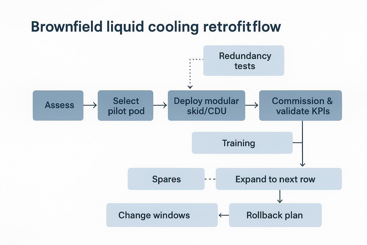
Phased cutovers with risk controls
A practical phased approach looks like:
-
Stand up the pilot pod in a controlled zone.
-
Commission with load testing and confirm alarms and rollback procedures.
-
Expand to the next row or pod using the same BOM and commissioning checklist.
-
Repeat until the AI block is standardized.
Risk controls to keep the change window safe:
-
Choose cutovers that align with maintenance windows and staffing.
-
Keep a rollback plan that doesn’t require heroics.
-
Maintain clear interface boundaries between facility water and technology coolant.
-
Document “golden config” for alarms and setpoints.
Interoperability, permitting, and training
In brownfield sites, the non-technical work often decides the schedule:
-
Interoperability: confirm BMS/DCIM integration, Modbus/BACnet gateways, naming conventions, and cybersecurity posture.
-
Permitting: plumbing modifications, water treatment, and any changes to heat rejection equipment can trigger review.
-
Training: maintenance workflow changes (especially for immersion) require SOPs, safety procedures, and spare strategy.
Compliance and standards to watch
ASHRAE TC 9.9 guidance highlights
ASHRAE TC 9.9 remains the anchor reference for environmental envelopes and guidance for thermal management.
Two practical takeaways for liquid programs:
-
Treat inlet temperature classes and liquid temperature targets as a design contract between IT and facilities.
-
Align monitoring and resilience practices to how cold-plate systems actually fail (flow loss, sensor drift, microleaks), not just room temperature excursions.
For a liquid-focused perspective, ASHRAE Journal’s “Liquid Cooling Cold Plates” (2025) is a useful starting point.
OCP/OAI/Open19 interoperability notes
Interoperability is moving from “nice to have” to procurement language in 2026 AI buildouts.
What to validate regardless of the ecosystem you follow:
-
CDU and skid telemetry supports your BMS/DCIM integration approach.
-
Interfaces and naming conventions are documented (protocols, tags, alarm taxonomy).
-
Vendor boundaries are clear for responsibility during incidents (MTTR ownership is a contract issue).
If you’re adopting open hardware frameworks (e.g., OCP) alongside liquid cooling, ensure your mechanical/electrical standards and your thermal control model are reconciled early—before the first pod is replicated.
Refrigerant and water regulations
Two themes show up repeatedly in operator planning:
-
Refrigerant transition risk: regulations and phasedowns (e.g., U.S. HFC reduction programs) can change equipment choices and long-term serviceability.
-
Water accounting pressure: even where towers are permitted, more stakeholders want visible WUE tracking and reduction plans.
The practical operator response is to treat compliance as a design input: metering, documentation, and lifecycle service plans should be part of the initial spec.
Conclusion
The fastest path to liquid in 2026 isn’t a full-site rebuild. It’s a disciplined, KPI-driven rollout:
-
Set your density decision thresholds and define what “stable” means (inlet temps, alarms, ΔT, approach temps).
-
Choose an architecture that matches your retrofit reality: RDHx as a bridge, DTC for high-density production, immersion where operations and hardware can standardize.
-
Track KPIs as a bundle: PUE (energy), WUE (water), and ERF (reuse potential), plus uptime-aligned operational telemetry.
If you’re staging AI blocks in an existing facility, prioritize a pilot pod with production-grade controls: validate KPIs, test redundancy and leak detection, and only then scale by repeating a standardized design.
For teams that want a structured way to package and replicate the liquid boundary (CDU + skid + monitoring) across sites, Coolnet’s liquid cooling resources—and its integrated deployment approach for multi-site rollouts—provide a useful reference point.


 IPv6 network supported