
 English
 中文
中文 العربية
 español
Introduction
This guide is for data center operators and facilities teams planning, expanding, or retrofitting liquid-cooled AI/HPC rows. If you’re carrying SLAs, chasing better PUE/WUE, and trying to scale rack density without turning every change into an outage window, CDU selection is no longer a “cooling” detail. It’s an uptime and commissioning problem.
AI/HPC loads map to CDU requirements in a pretty direct way: rack/pod capacity drives heat exchanger sizing, your temperature window sets ΔT, that ΔT sets flow, and your physical topology sets head (and whether you’ve got margin when filters load up or valves aren’t perfectly balanced). Controls matter because stability and alarm quality decide how fast ops can detect and contain failures.
By the end, you should be able to write RFP-ready criteria for a CDU that matches your density roadmap, integrates cleanly with DCIM/BMS, and is testable with acceptance criteria.
Thermal and hydraulic sizing
Define IT load and heat capture
Start with two numbers that have to be true on day one and still hold at the next refresh:
-
Peak IT kW per rack (and per pod), not the nameplate average.
-
Percent of heat captured to liquid, which depends on your cooling approach (direct-to-chip, rear-door assist, immersion) and what’s still riding on air.
Sizing mistakes usually come from mixing “steady-state average” with “peak worst-case.” For AI training clusters, peak and step changes matter because a liquid loop can go from stable to alarm conditions quickly if flow control or redundancy isn’t engineered for transients.
Temperature windows and ΔT targets
Your CDU is a translator between facility water and the technology cooling system (TCS). Operators typically treat facility water as its own loop (often called the facility water system, FWS) and keep the TCS isolated and tightly controlled; that separation is a common CDU role definition in sources like Airedale by Modine’s liquid cooling glossary (2025). For a quick architecture refresher, see Coolnet liquid cooling.
From a selection standpoint, you need to pin down:
-
TCS supply temperature range you can safely run without condensation or component limits.
-
Facility water window you can guarantee across seasons, economizer modes, and tower/chiller changeovers.
-
Design ΔT across the IT loop (TCS supply to TCS return).
A larger ΔT lowers flow for the same kW, which can reduce pump energy and ease distribution. The trade-off is component temperature limits and control stability. A too-small ΔT often drives high flow and makes head failures more likely when anything in the loop adds restriction.
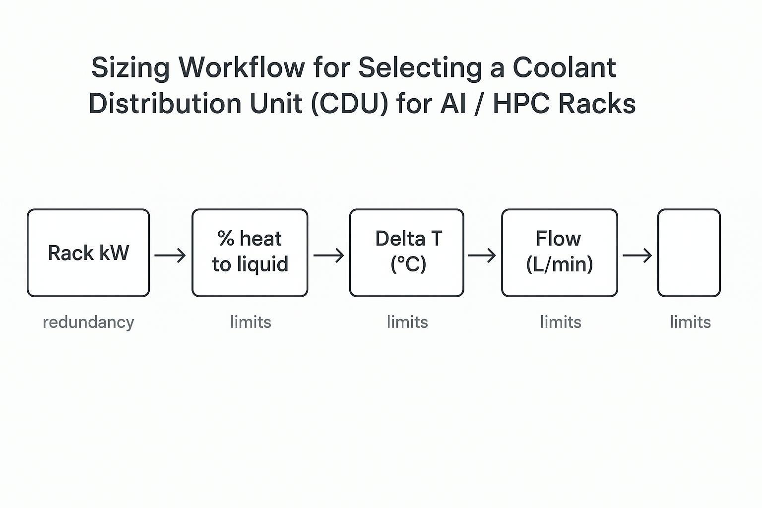
Flow-per-kW and pump head budget
A practical way to get from heat load to CDU hydraulics is to walk the chain and then validate it against your real topology.
As a starting heuristic for many direct-to-chip loops, some vendor guidance points to ~1.2–1.5 L/min per kW of heat load, with the reminder that the right value depends on cold plate design and allowable temperature rise; see Flex’s overview in JetCool’s CDU sizing discussion. Treat this as a first-pass estimate, not a specification.
The head budget is where “fine on paper” systems fail:
-
Distribution losses: manifolds, hose sets, QDs, valves, strainers, and any rack-level balancing.
-
Placement penalties: longer runs (gallery-to-row), elevation changes, and larger failure domains.
-
Degradation margin: filter loading, fouling, trapped air, and partial blockages that appear after commissioning.
Key Takeaway: If you don’t specify a minimum differential pressure at the required flow, you aren’t buying a CDU. You’re buying a heat exchanger with hope.
Architectures and deployment choices
Heat rejection: L2L, L2A, L2R
At a high level, you’re selecting how the CDU rejects heat:
-
Liquid-to-liquid (L2L): transfers heat from TCS to facility water. It’s the common choice when you have a stable facility loop and want strong isolation between water qualities.
-
Liquid-to-air (L2A): rejects heat to air. This can be useful where facility water isn’t available or where you want localized deployment, but it tends to shift constraints to airflow management and ambient conditions.
-
Liquid-to-refrigerant (L2R): uses a refrigerant loop. This can offer different temperature lift behavior but adds refrigeration interfaces and service considerations.
Selection isn’t about labels. It’s about what your site can guarantee: water availability, water temperature, heat rejection capacity, maintenance model, and how much variation you can tolerate without throttling IT. A practical way to align terminology and responsibilities is the dual-loop description in Liquid cooling CDU: optimizing data center efficiency.
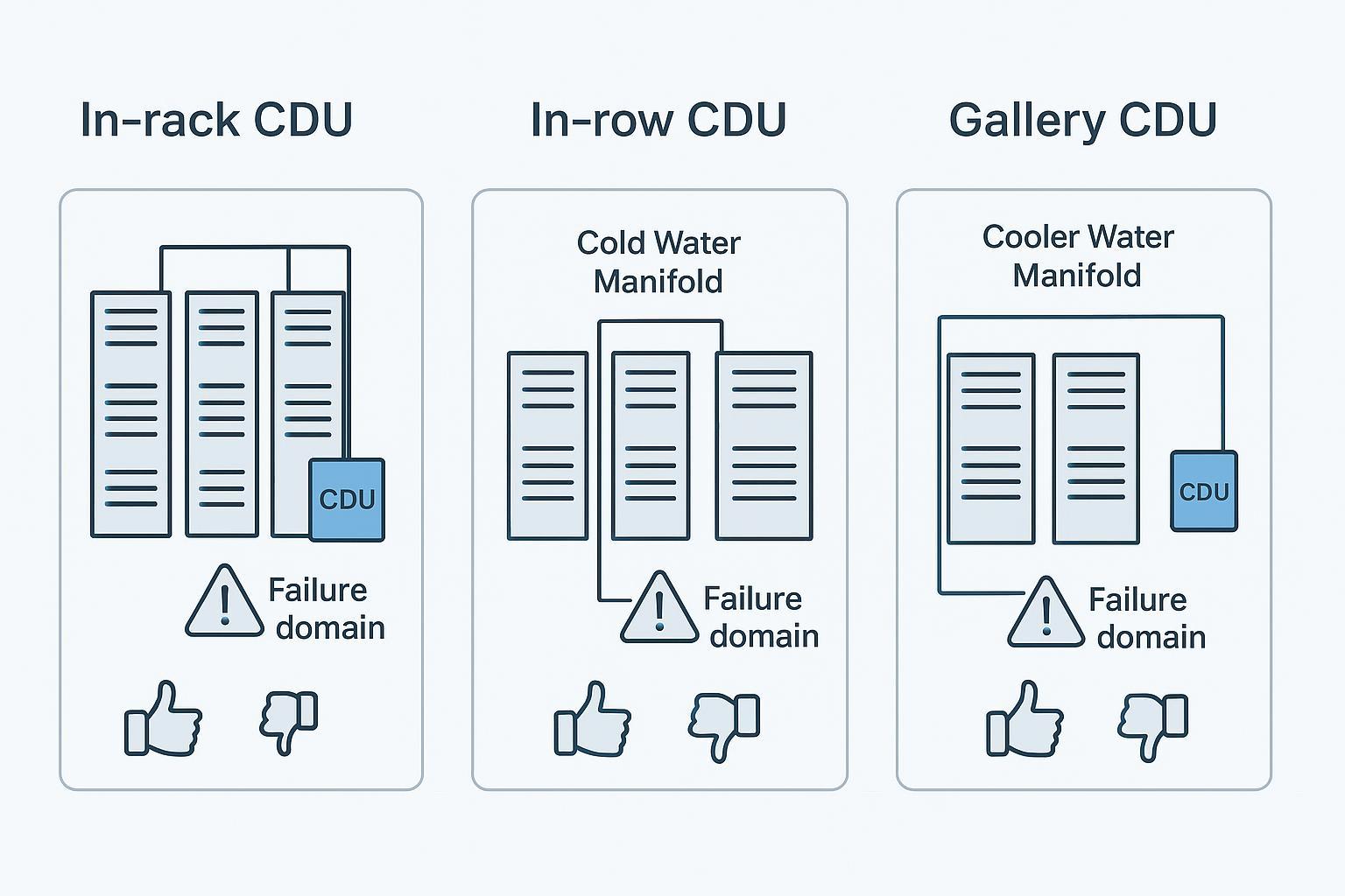
Placement: in-rack, in-row, gallery
Placement changes failure domain, service access, and your head budget.

Common operator trade-offs:
-
In-rack: tight failure domain and short runs, but more distributed assets to service and more rack space/power trade-offs.
-
In-row: good compromise for standardization; supports a row/pod approach and centralized service points.
-
Gallery: easier service access and potentially cleaner white space, but longer distribution runs, more head risk, and a larger blast radius if a single CDU affects many racks.
Workloads: direct-to-chip vs. immersion
Your workload and cooling method change what “good” looks like:
-
Direct-to-chip tends to be sensitive to flow control and stability at the cold plate, and it can force tighter pressure and differential pressure management.
-
Immersion shifts some concerns toward fluid compatibility, filtration strategy, and heat exchanger sizing across different fluids.
The CDU spec should reflect the method, not just the rack kW. If the cooling method changes in phase 2 of your AI rollout, your CDU selection should still be compatible with the new temperature and fluid requirements.
Reliability, water quality, serviceability
Filtration, chemistry, and materials
Reliability starts with keeping the TCS clean and chemically stable.
Practical selection criteria:
-
Filtration performance and maintainability (filter type, differential pressure monitoring, service intervals, bypass strategy).
-
Materials compatibility with your coolant chemistry (including corrosion considerations and any glycol or specialty fluids).
-
Isolation strategy between facility water quality and TCS purity.
If you can’t define water quality requirements and verify them during commissioning, you’ll see drift: fouling, degraded heat transfer, higher pump energy, and more nuisance alarms.
Leak detection and staged mitigation
Treat leak detection as part of the control system, not an accessory. The objective is staged response:
-
Detect early (sensors and trend-based anomalies).
-
Isolate the smallest possible segment.
-
Maintain safe flow/temperature for unaffected racks.
-
Recover with clear procedures and logged evidence.
Also define what “acceptable leakage risk” means operationally: sensor coverage, alarm thresholds, and who is paged for which events.
Redundancy and maintainability
Redundancy decisions should be explicit and testable:
-
Pump redundancy model (N+1 vs 2N) and what happens on pump failure.
-
Power source requirements for controls and pumps (UPS-backed where required by your risk model).
-
Maintenance approach: isolation valves, hot-swappable components where appropriate, and the ability to service filtration without draining large parts of the loop.
Maintainability is not only MTTR. It’s also whether the system can be serviced without introducing contamination or air into the TCS.
Controls and integration
Telemetry and open protocols
At minimum, require telemetry that makes the CDU observable as a control system:
-
TCS supply/return temperatures
-
flow rate
-
supply/return pressure and differential pressure
-
pump status and speed
-
valve positions (where relevant)
-
filter differential pressure
-
leak detection status
-
alarms with severity and clear setpoints
For integration, define protocols and data ownership up front. The CDU shouldn’t be a black box; operators need access to time-series data for diagnostics and audit.
Group control and stability
If you’re deploying multiple CDUs across a pod, ask how they coordinate:
-
What variable is being controlled (flow, differential pressure, supply temperature)?
-
How is stability maintained when racks ramp quickly?
-
What happens when one CDU drops out of service?
Group control has to be evaluated under transients, not just steady state. Your acceptance plan should include setpoint changes and load steps to verify no hunting, oscillation, or nuisance alarms.
DCIM/BMS and acceptance points
Define the handoff as part of the RFP: points list, update rates, alarm semantics, and whether control is supervisory (BMS sets targets) or local (CDU executes closed loop).
Coolnet example (neutral): Coolnet CDUs can expose cooling and power telemetry via Modbus RTU (optional TCP/IP) for DCIM/BMS trends and alarms; local PLC/HMI keeps loop control.
RFP checklist and acceptance tests (coolant distribution unit (CDU) selection)
Measurable specs and KPIs
Your RFP should ask for measurable values, not marketing labels.
Thermal and hydraulic:
-
Rated cooling capacity (kW) at defined facility water and TCS temperatures
-
Minimum achievable approach temperature difference at rated conditions
-
Required flow range and control accuracy
-
Minimum differential pressure / head at defined flow
Reliability and service:
-
Pump redundancy model and automatic failover behavior
-
Filtration rating and service method
-
Leak detection coverage and response options
-
Materials and coolant compatibility statement
Controls and integration:
-
Points list (temps, flow, pressures, alarms)
-
Supported protocols and security model
-
Event logging and time sync behavior
For selection framing, LiquidStack’s guide to choosing a CDU is a useful checklist-style reference. If you want an example of how vendors structure CDU options, see Coolnet CDUs for data center cooling.
Commissioning, rating, and dew point margin
Commissioning should prove the CDU meets rating in the way you will actually run it.
Acceptance criteria to specify:
-
Capacity test: demonstrate kW removal at your specified temperature conditions.
-
Flow and head test: show the CDU can hold the required flow while maintaining minimum differential pressure across representative distribution hardware.
-
Control stability test: step load and setpoint changes without oscillation.
-
Sensor validation: verify temperature, pressure, and flow sensor calibration against reference instruments.
Also specify a condensation control requirement in operational terms (your “dew point margin”). Even if you compute it differently across sites, the acceptance test is simple: demonstrate the coldest surface temperature in the loop stays above the site’s defined dew point threshold under worst-case humidity.
TCO levers and sustainability impacts
TCO isn’t only CapEx. For CDUs in AI pods, recurring cost drivers include:
-
Pump energy (driven by flow and head)
-
Heat rejection efficiency (tied to your temperature window and approach)
-
Maintenance labor and consumables (filters, fluid testing, spares)
-
Downtime risk and change windows
On sustainability, higher liquid ΔT and warmer facility water options can reduce chiller lift and improve efficiency, but only if the control scheme and acceptance testing prove stable operation.
Conclusion
-
CDU selection is an engineering translation: kW and temperature windows become ΔT, flow, and head, and then become controls and acceptance tests.
-
Placement and architecture decide your failure domains and whether your pump head budget is realistic.
-
Reliability lives in water quality, leak mitigation, redundancy, and service design, not in brochure ratings.
Next steps: validate peak loads and heat-capture assumptions, issue an RFP with measurable acceptance criteria, and plan a staged rollout that proves stability and service workflows before scaling pod-wide.


 IPv6 network supported